|
| Quantity: | |
|---|---|
WPH
■Removable measuring inserts are divided into four categories:DN40- 65,DN80-200,DN250-300 and DN400-500,easy for maintenance.
■Low pressure loss, high flow capacity, suitable for measuring supply line of water.
■Magnet-driven dry type structure, neat counters displaying clearly.
■360°rotating counter, convenient for reading.
■6 normal figure rolls to show reading.
■Epoxy resin powder coating and stainless steel fasteners, rust proofing to the largest extent, extending the service life.
■Wearable shaft and bearing system, prominently strengthen the meters long-term stability.
■Can be equiped with signal-transmitter counter , realizing outputs of multiple pulse signals (Non-magnetic; Photoelectric direct reading; Magnetoresistive) .
■Can be equipped with unremovable outer cover .
■Water temperature
Cold meters ≤50°C
Hot meters ≤90°C (DN 40-200)
■Water pressure ≤1.0 MPa /1.6MPa
Straight pipe is required
Need to add a strainer
Parallel installation
| Technical Data WPH | ||||||||||||
| Nor minal Diameter | DN | mm | 40 | 50 | 65 | 80 | 100 | 125 | ||||
| Norminal Flowrate | Q3 | m³/h | 40 | 40 | 63 | 100 | 160 | 250 | ||||
| Flow Turndown | Q3/Q1 | 80 | 80 | 80 | 80 | 80 | 80 | |||||
| Q2/Q1 | 1.6 | 1.6 | 1.6 | 1.6 | 1.6 | 1.6 | ||||||
| Overload Flowrate | Q4 | m³/h | 50 | 50 | 78.75 | 125 | 200 | 312.5 | ||||
| Transitional Flowrate | Q2 | m³/h | 0.8 | 0.8 | 1.26 | 2 | 3.2 | 5 | ||||
| Minimum Flowrate | Q1 | m³/h | 0.50 | 0.50 | 0.7875 | 1.25 | 2.00 | 3.125 | ||||
| Pressure Loss | △p 63 | △p 63 | △p 63 | △p 63 | △p 63 | △p 63 | ||||||
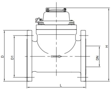
| Length | L | mm | 200 | 200 | 200 | 225 | 250 | 250 | ||||
| Height | H | mm | 206 | 210 | 218 | 280 | 290 | 310 | ||||
| Flange Connected | D | mm | 150 | 165 | 185 | 200 | 220 | 250 | ||||
| Screws Hole Diameter | pc .-mm | 4-Φ19 | 4-Φ19 | 4-Φ19 | 8-Φ19 | 8-Φ19 | 8-Φ19 | |||||
| Technical Data WPH | ||||||||||||
| Nor minal Diameter | DN | mm | 150 | 200 | 250 | 300 | 400 | 500 | ||||
| Norminal Flowrate | Q3 | m³/h | 400 | 630 | 630 | 1000 | 1600 | 2500 | ||||
| Flow Turndown | Q3 /Q1 | 80 | 80 | 80 | 80 | 50 | 50 | |||||
| Q2 /Q1 | 1.6 | 1.6 | 1.6 | 1.6 | 1.6 | 1.6 | ||||||
| Overload Flowrate | Q4 | m³/h | 500 | 787.5 | 787.5 | 1250 | 2000 | 3125 | ||||
| Transitional Flowrate | Q2 | m³/h | 8 | 12.6 | 12.6 | 20 | 51.2 | 80 | ||||
| Minimum Flowrate | Q1 | m³/h | 5.00 | 7.875 | 7.875 | 12.5 | 32 | 50 | ||||
| Pressure Loss | △p 63 | △p 63 | △p 63 | △p 63 | △p 63 | △p 63 | ||||||
| Length | Lmm | 300 | 350 | 450 | 500 | 600 | 800 | |||||
| Height | Hmm | mm | 320 | 364 | 450 | 500 | 580 | 715 | ||||
| Flange Connected | D | mm | 285 | 340 | 405 | 460 | 580 | 715 | ||||
| Screws Hole Diameter | pc .-mm | 8-Φ23 | 8/12-Φ23 | 12-Φ26 | 12-Φ26 | 16-Φ30 | 20-Φ34 | |||||